A | B | C | D | E | F | G | H | CH | I | J | K | L | M | N | O | P | Q | R | S | T | U | V | W | X | Y | Z | 0 | 1 | 2 | 3 | 4 | 5 | 6 | 7 | 8 | 9
This article has multiple issues. Please help improve it or discuss these issues on the talk page. (Learn how and when to remove these template messages)
|

Electric power transmission is the bulk movement of electrical energy from a generating site, such as a power plant, to an electrical substation. The interconnected lines that facilitate this movement form a transmission network. This is distinct from the local wiring between high-voltage substations and customers, which is typically referred to as electric power distribution. The combined transmission and distribution network is part of electricity delivery, known as the electrical grid.
Efficient long-distance transmission of electric power requires high voltages. This reduces the losses produced by strong currents. Transmission lines use either alternating current (AC) or direct current (DC). The voltage level is changed with transformers. The voltage is stepped up for transmission, then reduced for local distribution.
A wide area synchronous grid, known as an interconnection in North America, directly connects generators delivering AC power with the same relative frequency to many consumers. North America has four major interconnections: Western, Eastern, Quebec and Texas. One grid connects most of continental Europe.
Historically, transmission and distribution lines were often owned by the same company, but starting in the 1990s, many countries liberalized the regulation of the electricity market in ways that led to separate companies handling transmission and distribution.[2]
System

Most North American transmission lines are high-voltage three-phase AC, although single phase AC is sometimes used in railway electrification systems. DC technology is used for greater efficiency over longer distances, typically hundreds of miles. High-voltage direct current (HVDC) technology is also used in submarine power cables (typically longer than 30 miles (50 km)), and in the interchange of power between grids that are not mutually synchronized. HVDC links stabilize power distribution networks where sudden new loads, or blackouts, in one part of a network might otherwise result in synchronization problems and cascading failures.
Electricity is transmitted at high voltages to reduce the energy loss due to resistance that occurs over long distances. Power is usually transmitted through overhead power lines. Underground power transmission has a significantly higher installation cost and greater operational limitations, but lowers maintenance costs. Underground transmission is more common in urban areas or environmentally sensitive locations.
Electrical energy must typically be generated at the same rate at which it is consumed. A sophisticated control system is required to ensure that power generation closely matches demand. If demand exceeds supply, the imbalance can cause generation plant(s) and transmission equipment to automatically disconnect or shut down to prevent damage. In the worst case, this may lead to a cascading series of shutdowns and a major regional blackout.
The US Northeast faced blackouts in 1965, 1977, 2003, and major blackouts in other US regions in 1996 and 2011. Electric transmission networks are interconnected into regional, national, and even continent-wide networks to reduce the risk of such a failure by providing multiple redundant, alternative routes for power to flow should such shutdowns occur. Transmission companies determine the maximum reliable capacity of each line (ordinarily less than its physical or thermal limit) to ensure that spare capacity is available in the event of a failure in another part of the network.
Overhead

_line.jpg)
High-voltage overhead conductors are not covered by insulation. The conductor material is nearly always an aluminum alloy, formed of several strands and possibly reinforced with steel strands. Copper was sometimes used for overhead transmission, but aluminum is lighter, reduces yields only marginally and costs much less. Overhead conductors are supplied by several companies. Conductor material and shapes are regularly improved to increase capacity.
Conductor sizes range from 12 mm2 (#6 American wire gauge) to 750 mm2 (1,590,000 circular mils area), with varying resistance and current-carrying capacity. For large conductors (more than a few centimetres in diameter), much of the current flow is concentrated near the surface due to the skin effect. The center of the conductor carries little current but contributes weight and cost. Thus, multiple parallel cables (called bundle conductors) are used for higher capacity. Bundle conductors are used at high voltages to reduce energy loss caused by corona discharge.
Today, transmission-level voltages are usually 110 kV and above. Lower voltages, such as 66 kV and 33 kV, are usually considered subtransmission voltages, but are occasionally used on long lines with light loads. Voltages less than 33 kV are usually used for distribution. Voltages above 765 kV are considered extra high voltage and require different designs.
Overhead transmission wires depend on air for insulation, requiring that lines maintain minimum clearances. Adverse weather conditions, such as high winds and low temperatures, interrupt transmission. Wind speeds as low as 23 knots (43 km/h) can permit conductors to encroach operating clearances, resulting in a flashover and loss of supply.[3] Oscillatory motion of the physical line is termed conductor gallop or flutter depending on the frequency and amplitude of oscillation.
-
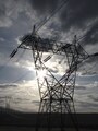 A five-hundred kilovolt (500 kV) three-phase transmission tower in Washington State, the line is bundled 3-ways
 -
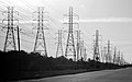 Three abreast electrical pylons in Webster, Texas


Underground
Electric power can be transmitted by underground power cables. Underground cables take up no right-of-way, have lower visibility, and are less affected by weather. However, cables must be insulated. Cable and excavation costs are much higher than overhead construction. Faults in buried transmission lines take longer to locate and repair.
In some metropolitan areas, cables are enclosed by metal pipe and insulated with dielectric fluid (usually an oil) that is either static or circulated via pumps. If an electric fault damages the pipe and leaks dielectric, liquid nitrogen is used to freeze portions of the pipe to enable draining and repair. This extends the repair period and increases costs. The temperature of the pipe and surroundings are monitored throughout the repair period.[4][5][6]
Underground lines are limited by their thermal capacity, which permits less overload or re-rating lines. Long underground AC cables have significant capacitance, which reduces their ability to provide useful power beyond 50 miles (80 kilometres). DC cables are not limited in length by their capacitance.
History

Commercial electric power was initially transmitted at the same voltage used by lighting and mechanical loads. This restricted the distance between generating plant and loads. In 1882, DC voltage could not easily be increased for long-distance transmission. Different classes of loads (for example, lighting, fixed motors, and traction/railway systems) required different voltages, and so used different generators and circuits.[7][8]
Thus, generators were sited near their loads, a practice that later became known as distributed generation using large numbers of small generators.[9]
Transmission of alternating current (AC) became possible after Lucien Gaulard and John Dixon Gibbs built what they called the secondary generator, an early transformer provided with 1:1 turn ratio and open magnetic circuit, in 1881.
The first long distance AC line was 34 kilometres (21 miles) long, built for the 1884 International Exhibition of Electricity in Turin, Italy. It was powered by a 2 kV, 130 Hz Siemens & Halske alternator and featured several Gaulard transformers with primary windings connected in series, which fed incandescent lamps. The system proved the feasibility of AC electric power transmission over long distances.[8]
The first commercial AC distribution system entered service in 1885 in via dei Cerchi, Rome, Italy, for public lighting. It was powered by two Siemens & Halske alternators rated 30 hp (22 kW), 2 kV at 120 Hz and used 19 km of cables and 200 parallel-connected 2 kV to 20 V step-down transformers provided with a closed magnetic circuit, one for each lamp. A few months later it was followed by the first British AC system, serving Grosvenor Gallery. It also featured Siemens alternators and 2.4 kV to 100 V step-down transformers – one per user – with shunt-connected primaries.[10]
Working to improve what he considered an impractical Gaulard-Gibbs design, electrical engineer William Stanley, Jr. developed the first practical series AC transformer in 1885.[11] Working with the support of George Westinghouse, in 1886 he demonstrated a transformer-based AC lighting system in Great Barrington, Massachusetts. It was powered by a steam engine-driven 500 V Siemens generator. Voltage was stepped down to 100 volts using the Stanley transformer to power incandescent lamps at 23 businesses over 4,000 feet (1,200 m).[12] This practical demonstration of a transformer and alternating current lighting system led Westinghouse to begin installing AC systems later that year.[11]
In 1888 the first designs for an AC motor appeared. These were induction motors running on polyphase current, independently invented by Galileo Ferraris and Nikola Tesla. Westinghouse licensed Tesla's design. Practical three-phase motors were designed by Mikhail Dolivo-Dobrovolsky and Charles Eugene Lancelot Brown.[13] Widespread use of such motors were delayed many years by development problems and the scarcity of polyphase power systems needed to power them.[14][15]

In the late 1880s and early 1890s smaller electric companies merged into larger corporations such as Ganz and AEG in Europe and General Electric and Westinghouse Electric in the US. These companies developed AC systems, but the technical difference between direct and alternating current systems required a much longer technical merger.[16] Alternating current's economies of scale with large generating plants and long-distance transmission slowly added the ability to link all the loads. These included single phase AC systems, poly-phase AC systems, low voltage incandescent lighting, high-voltage arc lighting, and existing DC motors in factories and street cars. In what became a universal system, these technological differences were temporarily bridged via the rotary converters and motor-generators that allowed the legacy systems to connect to the AC grid.[16][17] These stopgaps were slowly replaced as older systems were retired or upgraded.
The first transmission of single-phase alternating current using high voltage came in Oregon in 1890 when power was delivered from a hydroelectric plant at Willamette Falls to the city of Portland 14 miles (23 km) down river.[18] The first three-phase alternating current using high voltage took place in 1891 during the international electricity exhibition in Frankfurt. A 15 kV transmission line, approximately 175 km long, connected Lauffen on the Neckar and Frankfurt.[10][19]
Transmission voltages increased throughout the 20th century. By 1914, fifty-five transmission systems operating at more than 70 kV were in service. The highest voltage then used was 150 kV.[20] Interconnecting multiple generating plants over a wide area reduced costs. The most efficient plants could be used to supply varying loads during the day. Reliability was improved and capital costs were reduced, because stand-by generating capacity could be shared over many more customers and a wider area. Remote and low-cost sources of energy, such as hydroelectric power or mine-mouth coal, could be exploited to further lower costs.[7][10]
The 20th century's rapid industrialization made electrical transmission lines and grids critical infrastructure. Interconnection of local generation plants and small distribution networks was spurred by World War I, when large electrical generating plants were built by governments to power munitions factories.[21]
Bulk transmission

These networks use components such as power lines, cables, circuit breakers, switches and transformers. The transmission network is usually administered on a regional basis by an entity such as a regional transmission organization or transmission system operator.[22]
Transmission efficiency is improved at higher voltage and lower current. The reduced current reduces heating losses. Joule's first law states that energy losses are proportional to the square of the current. Thus, reducing the current by a factor of two lowers the energy lost to conductor resistance by a factor of four for any given size of conductor.
The optimum size of a conductor for a given voltage and current can be estimated by Kelvin's law for conductor size, which states that size is optimal when the annual cost of energy wasted in resistance is equal to the annual capital charges of providing the conductor. At times of lower interest rates and low commodity costs, Kelvin's law indicates that thicker wires are optimal. Otherwise, thinner conductors are indicated. Since power lines are designed for long-term use, Kelvin's law is used in conjunction with long-term estimates of the price of copper and aluminum as well as interest rates.
Higher voltage is achieved in AC circuits by using a step-up transformer. High-voltage direct current (HVDC) systems require relatively costly conversion equipment that may be economically justified for particular projects such as submarine cables and longer distance high capacity point-to-point transmission. HVDC is necessary for sending energy between unsynchronized grids.
A transmission grid is a network of power stations, transmission lines, and substations. Energy is usually transmitted within a grid with three-phase AC. Single-phase AC is used only for distribution to end users since it is not usable for large polyphase induction motors. In the 19th century, two-phase transmission was used but required either four wires or three wires with unequal currents. Higher order phase systems require more than three wires, but deliver little or no benefit.

While the price of generating capacity is high, energy demand is variable, making it often cheaper to import needed power than to generate it locally. Because loads often rise and fall together across large areas, power often comes from distant sources. Because of the economic benefits of load sharing, wide area transmission grids may span countries and even continents. Interconnections between producers and consumers enables power to flow even if some links are inoperative.
The slowly varying portion of demand is known as the base load and is generally served by large facilities with constant operating costs, termed firm power. Such facilities are nuclear, coal or hydroelectric, while other energy sources such as concentrated solar thermal and geothermal power have the potential to provide firm power. Renewable energy sources, such as solar photovoltaics, wind, wave, and tidal, are, due to their intermittency, not considered to be firm. The remaining or peak power demand, is supplied by peaking power plants, which are typically smaller, faster-responding, and higher cost sources, such as combined cycle or combustion turbine plants typically fueled by natural gas.
Long-distance transmission (hundreds of kilometers) is cheap and efficient, with costs of US$0.005–0.02 per kWh, compared to annual averaged large producer costs of US$0.01–0.025 per kWh, retail rates upwards of US$0.10 per kWh, and multiples of retail for instantaneous suppliers at unpredicted high demand moments.[23] New York often buys over 1000 MW of low-cost hydropower from Canada.[24] Local sources (even if more expensive and infrequently used) can protect the power supply from weather and other disasters that can disconnect distant suppliers.

Hydro and wind sources cannot be moved closer to big cities, and solar costs are lowest in remote areas where local power needs are nominal. Connection costs can determine whether any particular renewable alternative is economically realistic. Costs can be prohibitive for transmission lines, but high capacity, long distance super grid transmission network costs could be recovered with modest usage fees.
Grid input
At power stations, power is produced at a relatively low voltage between about 2.3 kV and 30 kV, depending on the size of the unit. The voltage is then stepped up by the power station transformer to a higher voltage (115 kV to 765 kV AC) for transmission.
In the United States, power transmission is, variously, 230 kV to 500 kV, with less than 230 kV or more than 500 kV as exceptions.
The Western Interconnection has two primary interchange voltages: 500 kV AC at 60 Hz, and ±500 kV (1,000 kV net) DC from North to South (Columbia River to Southern California) and Northeast to Southwest (Utah to Southern California). The 287.5 kV (Hoover Dam to Los Angeles line, via Victorville) and 345 kV (Arizona Public Service (APS) line) are local standards, both of which were implemented before 500 kV became practical.
Losses
Transmitting electricity at high voltage reduces the fraction of energy lost to Joule heating, which varies by conductor type, the current, and the transmission distance. For example, a 100 mi (160 km) span at 765 kV carrying 1000 MW of power can have losses of 0.5% to 1.1%. A 345 kV line carrying the same load across the same distance has losses of 4.2%.[25] For a given amount of power, a higher voltage reduces the current and thus the resistive losses. For example, raising the voltage by a factor of 10 reduces the current by a corresponding factor of 10 and therefore the losses by a factor of 100, provided the same sized conductors are used in both cases. Even if the conductor size (cross-sectional area) is decreased ten-fold to match the lower current, the losses are still reduced ten-fold using the higher voltage.

While power loss can also be reduced by increasing the wire's conductance (by increasing its cross-sectional area), larger conductors are heavier and more expensive. And since conductance is proportional to cross-sectional area, resistive power loss is only reduced proportionally with increasing cross-sectional area, providing a much smaller benefit than the squared reduction provided by multiplying the voltage.
Long-distance transmission is typically done with overhead lines at voltages of 115 to 1,200 kV. At higher voltages, where more than 2,000 kV exists between conductor and ground, corona discharge losses are so large that they can offset the lower resistive losses in the line conductors. Measures to reduce corona losses include larger conductor diameter, hollow cores[26] or conductor bundles.
Factors that affect resistance and thus loss include temperature, spiraling, and the skin effect. Resistance increases with temperature. Spiraling, which refers to the way stranded conductors spiral about the center, also contributes to increases in conductor resistance. The skin effect causes the effective resistance to increase at higher AC frequencies. Corona and resistive losses can be estimated using a mathematical model.[27]
US transmission and distribution losses were estimated at 6.6% in 1997,[28] 6.5% in 2007[28] and 5% from 2013 to 2019.[29] In general, losses are estimated from the discrepancy between power produced (as reported by power plants) and power sold; the difference constitutes transmission and distribution losses, assuming no utility theft occurs.
As of 1980, the longest cost-effective distance for DC transmission was 7,000 kilometres (4,300 miles). For AC it was 4,000 kilometres (2,500 miles), though US transmission lines are substantially shorter.[23]
In any AC line, conductor inductance and capacitance can be significant. Currents that flow solely in reaction to these properties, (which together with the resistance define the impedance) constitute reactive power flow, which transmits no power to the load. These reactive currents, however, cause extra heating losses. The ratio of real power transmitted to the load to apparent power (the product of a circuit's voltage and current, without reference to phase angle) is the power factor. As reactive current increases, reactive power increases and power factor decreases.
For transmission systems with low power factor, losses are higher than for systems with high power factor. Utilities add capacitor banks, reactors and other components (such as phase-shifters; static VAR compensators; and flexible AC transmission systems, FACTS) throughout the system help to compensate for the reactive power flow, reduce the losses in power transmission and stabilize system voltages. These measures are collectively called 'reactive support'.
Transposition
Current flowing through transmission lines induces a magnetic field that surrounds the lines of each phase and affects the inductance of the surrounding conductors of other phases. The conductors' mutual inductance is partially dependent on the physical orientation of the lines with respect to each other. Three-phase lines are conventionally strung with phases separated vertically. The mutual inductance seen by a conductor of the phase in the middle of the other two phases is different from the inductance seen on the top/bottom.
Unbalanced inductance among the three conductors is problematic because it may force the middle line to carry a disproportionate amount of the total power transmitted. Similarly, an unbalanced load may occur if one line is consistently closest to the ground and operates at a lower impedance. Because of this phenomenon, conductors must be periodically transposed along the line so that each phase sees equal time in each relative position to balance out the mutual inductance seen by all three phases. To accomplish this, line position is swapped at specially designed transposition towers at regular intervals along the line using various transposition schemes.
Subtransmission


Subtransmission runs at relatively lower voltages. It is uneconomical to connect all distribution substations to the high main transmission voltage, because that equipment is larger and more expensive. Typically, only larger substations connect with this high voltage. Voltage is stepped down before the current is sent to smaller substations. Subtransmission circuits are usually arranged in loops so that a single line failure does not stop service to many customers for more than a short time.
Loops can be normally closed, where loss of one circuit should result in no interruption, or normally open where substations can switch to a backup supply. While subtransmission circuits are usually carried on overhead lines, in urban areas buried cable may be used. The lower-voltage subtransmission lines use less right-of-way and simpler structures; undergrounding is less difficult.
No fixed cutoff separates subtransmission and transmission, or subtransmission and distribution. Their voltage ranges overlap. Voltages of 69 kV, 115 kV, and 138 kV are often used for subtransmission in North America. As power systems evolved, voltages formerly used for transmission were used for subtransmission, and subtransmission voltages became distribution voltages. Like transmission, subtransmission moves relatively large amounts of power, and like distribution, subtransmission covers an area instead of just point-to-point.[30]
Transmission grid exit
Substation transformers reduce the voltage to a lower level for distribution to customers. This distribution is accomplished with a combination of sub-transmission (33 to 138 kV) and distribution (3.3 to 25 kV). Finally, at the point of use, the energy is transformed to end-user voltage (100 to 4160 volts).
Advantage of high-voltage transmission
High-voltage power transmission allows for lesser resistive losses over long distances. This efficiency delivers a larger proportion of the generated power to the loads.


In a simplified model, the grid delivers electricity from an ideal voltage source with voltage , delivering a power ) to a single point of consumption, modelled by a resistance , when the wires are long enough to have a significant resistance .


If the resistances are in series with no intervening transformer, the circuit acts as a voltage divider, because the same current runs through the wire resistance and the powered device. As a consequence, the useful power (at the point of consumption) is:


Should an ideal transformer convert high-voltage, low-current electricity into low-voltage, high-current electricity with a voltage ratio of (i.e., the voltage is divided by and the current is multiplied by in the secondary branch, compared to the primary branch), then the circuit is again equivalent to a voltage divider, but the wires now have apparent resistance of only

Text je dostupný za podmienok Creative
Commons Attribution/Share-Alike License 3.0 Unported; prípadne za ďalších
podmienok.
Podrobnejšie informácie nájdete na stránke Podmienky
použitia.